Implementing a Sound-Synthesis Instrument
Specification
The Orchestra Editor for digital sound synthesis allows you to design a scheme of waveforms
and instruments, then use this scheme to generate sounds.
The instructions on this page will guide you toward creating an orchestra file named VibratoOrch.xml.
The orchestra will contain one instrument. This instrument emulates the vibrato effect obtained on early electronic
organs.
The one instrument in VibratoOrch.xml will be built around an audio-rate oscillator.
The audio-rate oscillator's amplitude will be modulated by a sustained envelope with 50-msec attack and release durations.
The audio-rate oscillator's frequency will be modulated by a low-frequency oscillator generating a sine wave whose output
is exponentially converted.
The waveform of the audio-rate oscillator will be a Rounded Sawtooth wave with 16 harmonics.
This instrument will have four custom parameters:
- P7: Amplitude (0-32767)
- P8: Center Frequency in Hz.
- P9: Vibrato Rate in Hz.
- P10: Vibrato Depth in semitones
You will build VibratoOrch.xml in three iterations.
You are encouraged to test each iteration before proceeding to the next.
- Iteration #1 implements the core audio-rate oscillator and its output box. These units are sufficient to generate a wave file, though without an envelope the sound will begin and end with pops.
- Iteration #2 drives the audio-rate oscillator's amplitude input with an envelope. The pops will go away but the vibrato is yet to come.
- Iteration #3 incorporates the sub-audio frequency-modulation components necessary to produce vibrato.
Creating an Orchestra
Initially, the orchestra editor should resemble Figure 1.
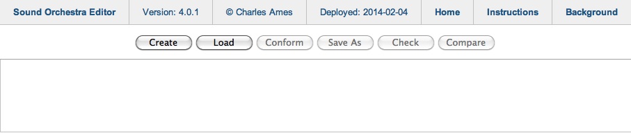
Figure 1: The orchestra editor without a file.
To create a new orchestra, click on ![]() and use the file chooser to locate
your working directory. Entire the filename “WaveformOrch.xml”, then click on
and use the file chooser to locate
your working directory. Entire the filename “WaveformOrch.xml”, then click on ![]() .
.
Once the file is successfully created, the orchestra editor will display the file path and the topmost component of the configuration scheme. This new display is shown in Figure 2.
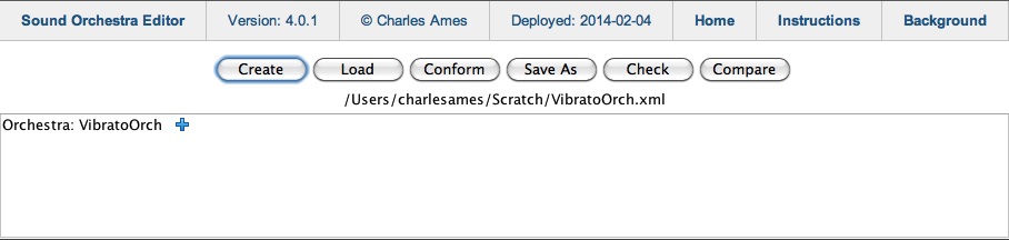
Figure 2: The applet after
WaveformOrch.xml has been loaded.
Editing Orchestra Attributes
To the right of the Orchestra: VibratoOrch component is a show-content icon ( ).
Clicking on this icon reveals the child items shown in Figure 3.
Notice that the show/expand icon toggles to a hide/collapse icon (
).
Clicking on this icon reveals the child items shown in Figure 3.
Notice that the show/expand icon toggles to a hide/collapse icon ( ).
).
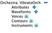
Figure 3: Expanding the Orchestra component reveals five child items.
Expand Attributes by clicking on the item's icon.
This action reveals the document-attribute editing panel pictured in Figure 4.
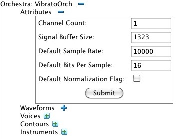
Figure 4: Expanding the Attributes component reveals an attribute-editing panel.
Attribute panels are the exception to the practice of saving changes immediately to file.
Within any attribute panel, you make whatever attribute changes you wish and then click on ![]() .
The editor checks your choices.
Only if it agrees with these choices does the editor save the changed attribute values to file.
.
The editor checks your choices.
Only if it agrees with these choices does the editor save the changed attribute values to file.
There are five document attributes:
- Channel Count — Configures the wavefile output as mono (1) or stereo (2).
- Signal Buffer Size — Leave this at 512 unless you have a good reason to change it.
- Default Sample Rate — The number of samples per second, per channel. Test tones internal to the orchestra employ this sampling rate. Used for note lists only when the note list does not explicitly state its own sampling rate.
- Default Bits per Sample — Configures the wavefile output as 16-bit or 32-bit precision. This value is used for note lists only when the note list does not explicitly state its own bits per sample. Test tones internal to the orchestra always employ 16-bit precision.
- Default Normalization Flag — indicates whether or not output should be normalized so that the maximum sample amplitude is 32767. If so, output is first written to a temporary wavefile with 32-bit precision, then a second permanent wavefile is generated with the requested sample precision. This flag is used for note lists only when the note list does not explicitly provide its own normalization flag. Test tones internal to the orchestra are never normalized.
Change the Default Sample Rate to 44100 and click on ![]() .
The display should now resemble Figure 5.
.
The display should now resemble Figure 5.
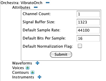
Figure 5: The attribute-editing panel with the Default Sample Rate changed from 10000 to 44100.
Complete this step by hiding () the attributes panel,
Creating a Waveform
Expand () the Waveforms collection.
The editor should now appear as pictured in Figure 6.
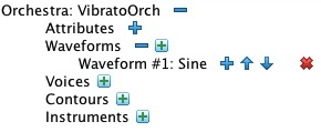
Figure 6: Expanding the Waveforms collection reveals a list of Waveform items.
Notice that Waveform #1: Sine was automatically included when you created VibratoOrch.xml.
It is now time to create Waveform #2: Rounded Sawtooth.
Start by clicking on the Waveforms collection's (add new item) icon.
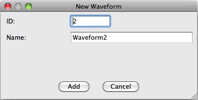
Figure 7: The New Waveform dialog.
Up pops the New Waveform dialog shown in Figure 7.
Accept the new waveform
ID of 2 but change the waveform name from “Waveform2” to “Rounded Sawtooth”.
Click on ![]() . Notice that a new item, Waveform #2: Rounded Sawtooth,
now appears in the Waveforms collection. Expand () this item.
The editor should now resemble Figure 8.
. Notice that a new item, Waveform #2: Rounded Sawtooth,
now appears in the Waveforms collection. Expand () this item.
The editor should now resemble Figure 8.
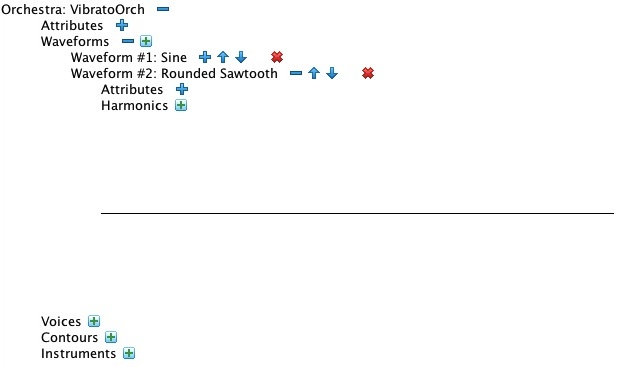
Figure 8: Details of Waveform #2: Rounded Sawtooth.
The next step adds a harmonic to the waveform. You will need to repeat this step 16 times, once for each of 16 amplitude values given for
the Rounded Sawtooth harmonics. To create a harmonic, click on the add-new-item icon ( ) for
Waveform #2: Rounded Sawtooth. Then respond as appropriate to the New Harmonic
dialog shown in Figure 9.
) for
Waveform #2: Rounded Sawtooth. Then respond as appropriate to the New Harmonic
dialog shown in Figure 9.
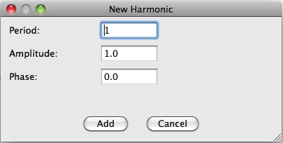
Figure 9: The New Harmonic dialog.
Now that we've finished creating Waveform #2, the editor should resemble Figure 10.
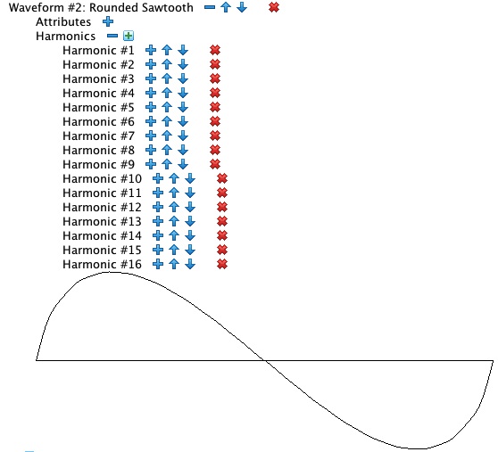
Figure 10: Waveform #2: Rounded Sawtooth with sixteen harmonics.
Collapse () the Waveforms collection in preparation for the next step.
Creating an Instrument
To create Instrument #1, click on the add-new-item icon () for the
Instruments collection. Up will pop the New Instrument
dialog shown in Figure 11.
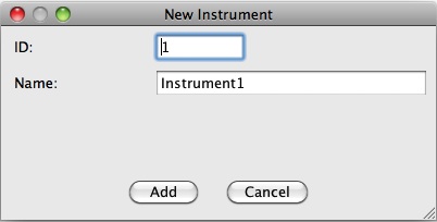
Figure 11: The New Instrument dialog.
Accept the default instrument ID of 1, but change the instrument name from “Instrument1”
to “Vibrato”.
Click on ![]() . Notice that a new item, Instrument #1: Vibrato,
now appears in the Instruments collection. Expand () this item.
The editor should now resemble Figure 12.
. Notice that a new item, Instrument #1: Vibrato,
now appears in the Instruments collection. Expand () this item.
The editor should now resemble Figure 12.
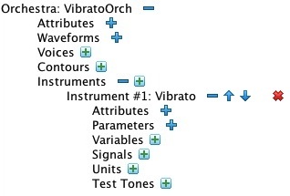
Figure 12: The newly created Instrument #1: Vibrato item.
Instrument Parameters
Expand () the Parameters collection under Instrument #1.
Doing this will reveal the six parameters that are mandatory to all instruments. Figure 13 shows these mandatory
parameters.
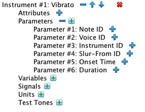
Figure 13: Expanding the Parameters collection.
To declare a custom parameter, click on the on the add-new-item icon () for the
Parameters collection, then respond to the New Parameter dialog shown in
Figure 14.
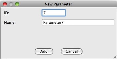
Figure 14: The New Parameter dialog.
You'll need to repeat this step for each of the parameters listed at the top of this page. When you've done so, the editor should resemble Figure 15.
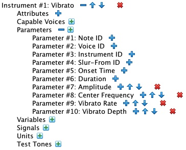
Figure 15: Instrument #1's Parameters collection now includes four custom parameters.
Collapse () the Parameters collection, which does not figure in the next steps.
Iteration #1: Core Units
We begin by creating the instrument's core units, which are the audio-rate oscillator and its output-to-channel unit. We start by declaring the signal through which the oscillator will transmit data to the output-to-channel unit. The oscillator will initially be configured to receive data directly from parameters. This will enable us to test the core units before introducing greater complexity.
Data Conduit
To declare an instrument-level signal, click on the on the add-new-item icon () for the
Signals collection, then respond to the New Signal dialog shown in
Figure 16. Accept the default signal ID (1) but change the signal name from “Signal1”
to “Audio”.
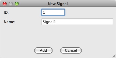
Figure 16: The New Signal dialog.
The editor should resemble Figure 17.
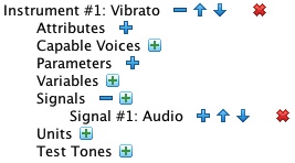
Figure 17: Instrument #1's Signals collection now includes a signal named “Audio”.
Units
To create a unit, click on the on the add-new-item icon () for the
Units collection, then respond to the New Unit dialog shown in
Figure 18. Accept the default unit sequence number (1) but use the drop-down to change the unit type from “Add”
to “Oscillator”.
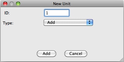
Figure 18: The New Unit dialog.
A new item, Unit #1: Oscillator will appear in the Units collection.
Expand () this unit, then expand the unit's Arguments collection.
The editor should now resemble Figure 19.
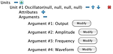
Figure 19: Unit #1: Oscillator is here expanded to show the details of its Arguments collection.
Click on ![]() for Argument #1: Output.
Up pops the link-argument dialog shown in Figure 20.
for Argument #1: Output.
Up pops the link-argument dialog shown in Figure 20.
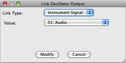
Figure 20: The link-argument dialog for Argument #1: Output of Unit #1: Oscillator.
Accept the Link Type and Value settings and click on the dialog's
![]() button. Modify the remaining three arguments:
button. Modify the remaining three arguments:
- For Argument #2: Amplitude, the Link Type should be “Parameter” and the Value should be “P7: Amplitude”.
- For Argument #3: Frequency, the Link Type should be “Parameter” and the Value should be “P8: Center Frequency”.
- For Argument #4: Waveform, the Link Type should be “Constant” and the Value should be “2” (referencing Waveform #2: Rounded Sawtooth).
When you've modified all four arguments, the units collection should resemble Figure 21.
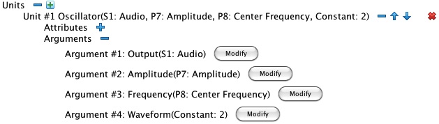
Figure 21: Unit #1: Oscillator now has every member of its Arguments collection linked to a data conduit.
To complete the core units, you need to create an additional unit with ID “2” and Type “Output”. This type of unit has two arguments. For Argument #1: Signal, the Link Type should be “Instrument Signal” and the Value should be “S1: Audio”. For Argument #2: Channel, the Link Type should be “Constant” and the Value should be “0” (the only acceptable channel id for monaural output). Once you've made these changes, the editor should resemble Figure 22.
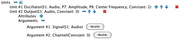
Figure 22: Unit #2: Output.
Now that you're finished creating and linking Unit #2: Output, collapse () all detail under the item.
Instrument #1 doesn't yet do everything we intend for it, but it at least implements enough functionality to produce a tone.
Time to Test
You should first test whether the orchestra is well-formed.
Do this by clicking on the ![]() in the row of buttons across the top of the editor.
This button causes the Sound engine to verify that every argument of every unit in every instrument is properly linked
to an appropriate data conduit. The engine also checks for things like uninitialized or unconsumed signals. If everything checks
out you will receive an announcement of success. If not, the editor will identify where the problems are.
in the row of buttons across the top of the editor.
This button causes the Sound engine to verify that every argument of every unit in every instrument is properly linked
to an appropriate data conduit. The engine also checks for things like uninitialized or unconsumed signals. If everything checks
out you will receive an announcement of success. If not, the editor will identify where the problems are.
The next test is to use your well-formed orchestra to generate a sample wave file. To do this you must first have a test-tone item. Fortunately you'll be able to re-use this test-tone item unaltered for future iterations.
To create a test tone item, click on the on the add-new-item icon () for the
Test Tones collection, then respond to the New Test Tone dialog shown in
Figure 23. We'll only be creating one test tone instance for Instrument #1,
so accept both defaults.
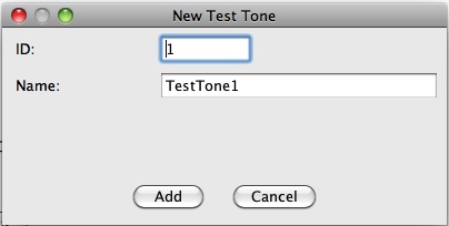
Figure 23: The New Test Tone dialog.
Assign the following values to each of Instrument #1's custom parameters:
- P7: Amplitude — 32000
- P8: Center Frequency — 220 (Hz.)
- P9: Vibrato Rate — 6 (Hz.)
- P10: Vibrato Depth — 0.5 (semitones peak-to-peak) (
To create a new test parameter assignment, click on the on the add-new-item icon () for the
Test Parameters collection. The editor will respond with a
New Test Parameter dialog. Select a parameter using the Parameter drop down and
enter the corresponding value in the Value field. Click on the dialog's
![]() button.
button.
Figure 24 shows Test Tone #1: TestTone1 with its components fully expanded. Notice that Duration is an attribute of the test-tone item. It defaults to one second, but you can modify it in the panel. Likewise you can modify each parameter's assigned value in the test parameter attribute panel.
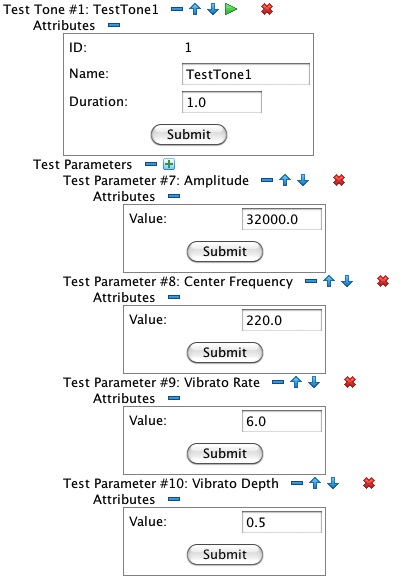
Figure 24: Test Tone #1: TestTone1, fully expanded.
To hear a test tone, you must first generate a wavefile.
Clicking on the the run icon ( ) initiates a progress dialog resembling Figure 25.
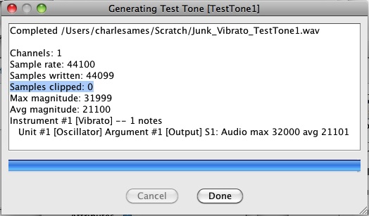
Figure 25: Test-Tone Progress Dialog.
This dialog contains a text field identifying the wavefile path, a progress bar, and two buttons.
You can click on ![]() to abort wavefile generation in progress.
Completing the synthesis run deactivates the
to abort wavefile generation in progress.
Completing the synthesis run deactivates the ![]() button and
activates the
button and
activates the ![]() button. The text field now contains
a report which includes, among other things, the maximum sample magnitude, the average sample magnitude, and the
number of clipped samples. You want the maximum sample magnitude to be as close as possible to 32767, but
no larger. You also want the number of clipped samples to be 0 (zero). A unit-by-unit summary of sample magnitudes
is also provided. If you can estimate the expected range of sample magnitudes coming out of each unit, then this summary
can be helpful in identifying unexpected behavior.
button. The text field now contains
a report which includes, among other things, the maximum sample magnitude, the average sample magnitude, and the
number of clipped samples. You want the maximum sample magnitude to be as close as possible to 32767, but
no larger. You also want the number of clipped samples to be 0 (zero). A unit-by-unit summary of sample magnitudes
is also provided. If you can estimate the expected range of sample magnitudes coming out of each unit, then this summary
can be helpful in identifying unexpected behavior.
Click on ![]() to return to the orchestra editor.
to return to the orchestra editor.
When the Sound engine has successfully generated a wavefile, a play-sound icon ( ) appears
just right of the run icon.
Clicking will toggle the icon to
) appears
just right of the run icon.
Clicking will toggle the icon to  and begin the tone. While the tone
is playing you can click on to stop it. When the tone completes,
toggles back to .
and begin the tone. While the tone
is playing you can click on to stop it. When the tone completes,
toggles back to .
You will notice that the sound begins and ends with an obnoxious pop. That's what we would expect from a tone with no envelope, so even though the sound is bad, the test is successful.
When you are done testing, collapse () all detail under Test Tone #1: TestTone1.
Iteration #2: Adding an Envelope
This second iteration simply inserts an envelope generator into the Instrument #1.
There is a mild challenge because new unit needs to go into position #1, which is presently occupied by the audio-rate
oscillator. The solution is to append the new unit onto the end of the collection, then use the  icon to nudge it up to where it belongs.
Clicking on the Unit collection's (add new item) icon.
In the ensuing New Unit dialog, accept the default ID value of
3 and use the Type drop down to select “EnvSust”. Click on ![]() .
.
Locate the (shift up) icon to the right of the newly created Unit #3: EnvSust item.
Clicking on causes the item to shift up one position, changing its legend to
Unit #2: EnvSust. Click on once again in the new position to move
the unit to the top of the collection.
The next steps are to link each argument of Unit #1: EnvSust to a data conduit.
- For Argument #1: Output, the Link Type should be “Instrument Signal” and the Value should be “S1: Audio”.
- For Argument #2: Attack Duration, the Link Type should be “Constant” and the Value should be “0.05”.
- For Argument #3: Amplitude, the Link Type should be “Parameter” and the Value should be “P7: Amplitude”.
- For Argument #4: Release Duration, the Link Type should be “Constant” and the Value should be “0.05”.
The final step is to relink each argument of Unit #2: Oscillator to a data conduit.
When you've completed all these steps, the unit arguments should be configured as shown in Figure 26.
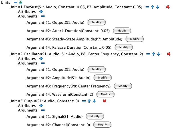
Figure 26: Instrument #1: Vibrato, upgraded to shape its audio-rate oscillator with an amplitude envelope.
Time to Test
Use the ![]() button to verify that the orchestra is still well formed.
button to verify that the orchestra is still well formed.
You can reuse Test Tone #1: TestTone1 unaltered; however, you must regenerate the wave file ()
before listening to the result ().
Iteration #3: Adding Frequency Modulation
Warning: The units in this iteration implement frequency modulation, but not of the kind used in John Chowning's method of Frequency Modulation Synthesis. I have no idea what might happen if you try to run this instrument with audio-rate vibrato frequencies.
Specification
This third and final iteration introduces a second oscillator operating at a sub-audio (control) frequency It then implements a transformation mapping the output from this sub-audio oscillator into the frequency domain. In the discussion which follows, let S = 12√2 represent the frequency ratio corresponding to one semitone. This quantity is available through the orchestra editor as the “Semitone” system variable.
The inputs to the sub-audio oscillator are governed by P9: Vibrato Rate and P10: Vibrato Depth. The oscillator amplitude is calculated as P10 / 2, while the oscillator frequency comes directly from P9. The oscillator waveform will be Waveform #1: Sine.
Output from the sub-audio oscillator will be transformed using two units. The first unit will raise S to an exponent, the oscillator output. The second unit will multiply the output of the first unit by P8: Center Frequency This transformation will generate a modulating signal in the frequency domain, with the following properties:
- The peak-to-trough ratio of the modulating signal will be R = SP10.
- The zero point of the sine wave maps to P8.
- The peak of the sine wave maps to P8 × 2√R.
- The trough of the sine wave maps to P8 / 2√R.
New Data Conduits
To implement the sub-audio oscillator and its transformation, Instrument #1 will need data conduits to hold (1) the modulating signal and (2) the rescaled vibrato depth.
For the modulating signal, click on the on the add-new-item icon () for the
Signals collection. A New Signal dialog will ensue.
Accept the default signal ID (2) but change the signal name from “Signal2” to “Modulator”.
Click on ![]() .
.
For the rescaled vibrato depth, click on the on the add-new-item icon () for the
Variables collection. A New Variable dialog will ensue.
Accept the default variable ID (1) but change the variable name from “Variable1” to “Semitones”.
Click on ![]() .
.
This completes our creation of data conduits. We now turn to units.
New Units
First create a unit that divides P9: Vibrato Rate in half.
Click on the Unit collection's (add new item) icon.
In the ensuing New Unit dialog, accept the default ID value of
4 and use the Type drop down to select “Multiply”.
Click on ![]() .
Use the icon to shift the newly created unit into position #2.
Link the new unit's arguments as follows:
.
Use the icon to shift the newly created unit into position #2.
Link the new unit's arguments as follows:
- For Argument #1: Output in Unit #2: Multiply, the Link Type should be “Instrument Variable” and the Value should be “V1: Semitones”.
- For Argument #2: Multiplicand in Unit #3: Multiply, the Link Type should be “Parameter” and the Value should be “P10: Vibrato Depth”.
- For Argument #3: Multiplier in Unit #3: Multiply, the Link Type should be “Constant” and the Value should be “0.5”.
Next create the sub-audio oscillator. Create a “Oscillator” unit, locating it in position 3. Link the new oscillator's arguments as follows:
- For Argument #1: Output, the Link Type should be “Instrument Signal” and the Value should be “S2: Modulator”.
- For Argument #2: Amplitude, the Link Type should be “Constant” and the Value should be “1”.
- For Argument #3: Frequency, the Link Type should be “Parameter” and the Value should be “P9: Vibrato Rate”.
- For Argument #4: Waveform, the Link Type should be “Constant” and the Value should be “1” (referencing Waveform #1: Sine).
Now create a “Power” unit, locating it in position 4. Link the unit arguments as follows:
- For Argument #1: Output in Unit #5: Power, the Link Type should be “Instrument Signal” and the Value should be “S2: Modulator”.
- For Argument #2: Base in Unit #5: Power, the Link Type should be “System Variable” and the Value should be “Semitone”.
- For Argument #3: Exponent in Unit #5: Power, the Link Type should be “Instrument Signal” and the Value should be “S2: Modulator”.
The fourth and last new unit wraps the modulating signal around the center frequency. Create a “Multiply” unit, locating it in position 5. Link the unit arguments as follows:
- For Argument #1: Output in Unit #6: Multiply, the Link Type should be “Instrument Signal” and the Value should be “S2: Modulator”.
- For Argument #2: Multiplicand in Unit #6: Multiply, the Link Type should be “Instrument Signal” and the Value should be “S2: Modulator”.
- For Argument #3: Multiplier in Unit #6: Multiply, the Link Type should be “Parameter” and the Value should be “P8: Center Frequency”.
Repointing the Audio-Rate Frequency
The final step in iteration #3 is to repoint the audio-rate oscillator's frequency argument to the new modulating signal.
Locate the audio-rate oscillator in its new position, Unit #6: Oscillator
Now expand () the Arguments collection.
Modify Argument #3: Frequency, changing the Link Type to “Instrument Signal”
and changing the Value to “S2: Modulator”.
When you've completed all these steps, Instrument #1: Vibrato should be configured as shown in Figure 27.
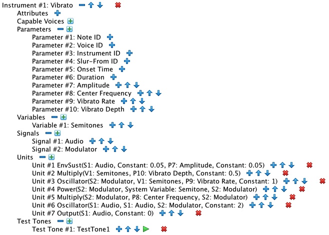
Figure 27: The completed Instrument #1: Vibrato.
Time to Test
Use the ![]() button to verify that the orchestra is still well formed.
button to verify that the orchestra is still well formed.
You can reuse Test Tone #1: TestTone1 unaltered; however, you must regenerate the wave file ()
before listening to the result ().
| © Charles Ames | Page created: 2014-02-22 | Last updated: 2017-08-15 |